Experiment 3 – Audio Amplifier

Michael Smith
ELEC 3030-RF Systems Lab
Date of Lab 3.2 and 3.4 - Friday, September 3, 2021, 1 p.m.
Date of Lab 3.6 - Friday, September 10, 2021, 1 p.m.
Experiment 3 – Audio Amplifier
Today’s Date - October 10, 2021
Introduction
Lab 3 was an introduction to Audio Amplifiers. An audio amplifier’s job is to boost the signal level for driving a speaker. That’s where gain comes into play. Gain is the comparing of how much voltage goes into a system versus how much voltage comes out. So, for an amplifier you want more voltage coming out than what’s going in, i.e., a large gain is very desirable. Since these labs are centered around audio amplifiers and AM radio signals, you also must take into consideration bandwidth and signal distortion. Bandwidth is not generally an issue at such low frequencies, but signal distortion can be important for sound quality. We need to know how different amplifiers effect each of these issues.
Throughout these various lab exercises we became familiar with, analyzed and constructed Common-Collector (CCamp), CE-CC two stage amp, class AB push-pull amp, CE-class AB two stage amp, Op-amp audio amplifier, Op-amp class AB two stage amp and the LM386 audio amp.
Each amplifier has its own positive and negative aspects that are desirable depending on the various situational needs. That’s why it’s necessary to become familiar with each of them.
In order to cut on redundancy and reduce the addition of unnecessary images, I have labeled my images the same as the images in the lab instructions. In other words, if the lab instructions say to recreate the circuit in Figure 3.4, I have labeled the circuit I recreated from the lab instructions, Figure 3.4. Likewise, if we are to recreate Table 3.3, I have labeled my Table 3.3 same with graphs. Since the person grading this paper is very familiar with the pre-lab and lab instructions, I don’t see the need to add the image that has to be recreated when the reader has that information in front of them. Also, I feel if you must compare lab instructions of Figure 3.3 to my Figure 3.3, it cuts down on confusion of numbering and labeling.
Step 3.1 & 3.2
In section 3.1 and 3.2 of our lab exercises, we were introduced to the buffer amplifier and two-stage BJT amplifier. These two sections educated us on the two different amplifiers plus we had to build several LTspice simulations and calculate quiescent power dissipation (PQ), Q point, Gain (A), and run several simulations varying different aspects of the circuits. For detailed information, simulations, calculations and answers proposed to various situations, see my Prelab 3 report.
Step 3.3
The overall goal of all these labs is to build a working AM radio connected to a loudspeaker. In part 3.3 of our lab, we had to build and test a two-stage amplifier. Our very first step was to solder wires to the input and the output of our loudspeaker, if it did not come already attached. This was not a difficult task. My T.A. inspected the loudspeaker and said it was significantly soldered. I applied an audio wave directly to the speaker. I connected the function generator to my speaker with the oscilloscope connected so I could observe the results. I set the function generator to create a 1kHz sinewave with an input signal amplitude (Vin) to 2Vpp. On the Oscilloscope my Vin registered an amplitude of 481.2mV, see Figure 1, this did produce a sound out of my speaker. I increased my Vin all the way up to 3.0V but I did not observe any increase in the volume.
The next step was to connect the function generator to the CE amp we built in Lab 2 and then connect the speaker. After this connection was made, I tested the speaker and heard a very faint sound. I next constructed a CC amplifier as instructed and connected it between the function generator and the speaker. I then conducted a sound check with a Vin of 1kHz, the output sound was good. The oscilloscope displayed a beautiful soundwave at 1.881 Vpp, see Figure 2.
The next step was to connect the CE amp to the CC amp and have that between the function generator and the loudspeaker. This connection produced a loud and clear sound. I used the oscilloscope to view the output signal. The signal was very noisy, but I was able to make adjustments where it was not noisy, but it was not a traditional sinewave, see Figure 3. I replaced the speaker with a 10Ω resistor and I used the oscilloscope to examine the input and the output signal at this level. My input amplitude was 20mV and my output amplitude was 1.4V, that means my gain was 70 V/V, see Table 3.1. I then determined my quiescent power dissipation (PQ) by feeding my voltage supply through a 100Ω resistor. The measured resistance of the resistor was 97.7Ω and I fed 9V through it, giving me a current of 92.11873 mA. That means PQ = (I)(V) = (92.11873 mA)(9V) = PQ = 0.82906858 watts.
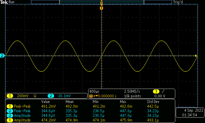

Figure 1 – Driving the speaker directly from the generator.
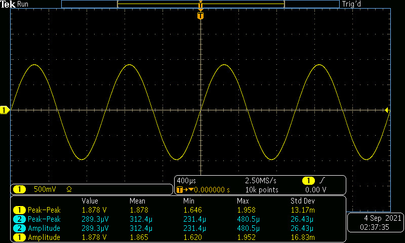
Figure 2 – Output signal while conducting a soundcheck with vin = 1kHz.
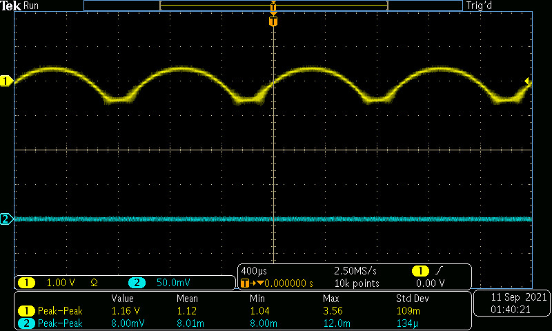
Figure 3 – Output signal with RL equals 10Ω and connected to CE amp and CC amp.
|
Output Amplitude |
1.4V |
|
Input Amplitude |
20mV |
|
Gain(V/V) |
70 |
Table 3.1 – Voltage amplitudes and gain for the two-stage amplifier terminated in a 10Ω load.
Step 3.4b
The CC amplifier of section 3.1 is called a class A amplifier. A Q-point is set, and regardless of whether there is a signal to amplify, power is dissipated in the amplifier. In contrast a basic class B amplifier, in a push-pull configuration has the efficiency advantage than that the npn BJT is only on during the positive half cycle, and the pnp BJT is only on during the negative half cycle. Therefore, it has little quiescent power dissipation in the transistor portion of the amplifier. A drawback to the class B amplifier, however, is that it takes roughly 0.7V to turn on the forward biased pn junctions in the BJTs, so the output signal can show significant distortions.
So next we looked at the class AB amplifier. The class AB amplifier solves the distortion problem, but it doesn’t have as high efficiency. A class AB amplifier is made by adding two diodes to a class B amplifier in the base bias string and that ensures that there is just sufficient voltage to turn on the pair of transistor’s pn junctions, and the output signal is far less distorted.
In part 3.4b of our lab I had to physically breadboard the class B push-pull amplifier with the 2N3904/2N3906 transistors as shown in Figure 3.11. I ran the supply voltage through a 100Ω resistor and adjusted the supply voltage to maintain 9V on the circuit side of this resistor. I checked the bias voltage and calculated the circuit’s quiescent dissipated power (PQ) to be 0.0080604 watts.
Next, I set the input level to 2V amplitude, you can see the waveform in Figure 4 and see that it is distorted.
I breadboarded the class AB push-pull amplifier by adding the diodes as shown in Figure 3.13. I checked the bias voltages with no input signal, and I measured the voltage to be 0.638V over a 100Ω resistor (94.6 Ω) and calculated the PQ to be 0.00408679, comparing this to my PQ from the class B push-pull amplifier you can see the PQ from the class AB push-pull amplifier is about half of what the PQ is from the class B push-pull amplifier.
I set the input level to 2V amplitude. You can see from Figure 5 that this is a nice clean sinewave output signal and not distorted like the output signal from the class B push-pull amplifier, see Figure 4 below. I then replace my 10Ω resistor with the speaker, from the sound I received from my loudspeaker, it was obvious that this amplifier would be sufficient for my radio. I had a good clear output sound. As I raised the voltage of the input signal, the sound from my speaker increased as well. I know the gain should be close to 1 but I got an output voltage of 200mVpp, this could be due to how the oscilloscope is taking readings. The readings from this oscilloscope has been wrong before.
I replaced the second stage CC amp of Figure 3.3 with my class AB push-pull amp. I inserted it between the generator and the speaker as was indicated in Figure 3.9, from our lab instructions, then I reduced my power level. In Table 3.2 you can see my output and input amplitude which gave me a gain of 2.488 V/V. I then conducted a sound check with the generator with the CE stage input set to 1kHz sinewave with amplitude 20mV. The sound from my speaker was nice and clear. I tested it from 10mVpp – 30mVpp, I could hear a clear sound at each step. As I increased the voltage the sound increased also.
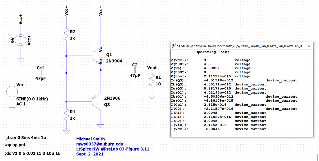
Figure 3.11 – A basic class B push-pull amplifier
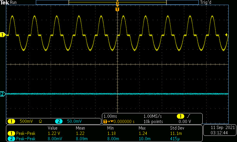
Figure 4 – Output signal from the class B push-pull amplifier
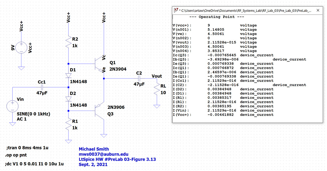 Figure 3.13 – A class AB push-pull amplifier. The diodes ensure the pair of transistor’s pn junctions are “on”.
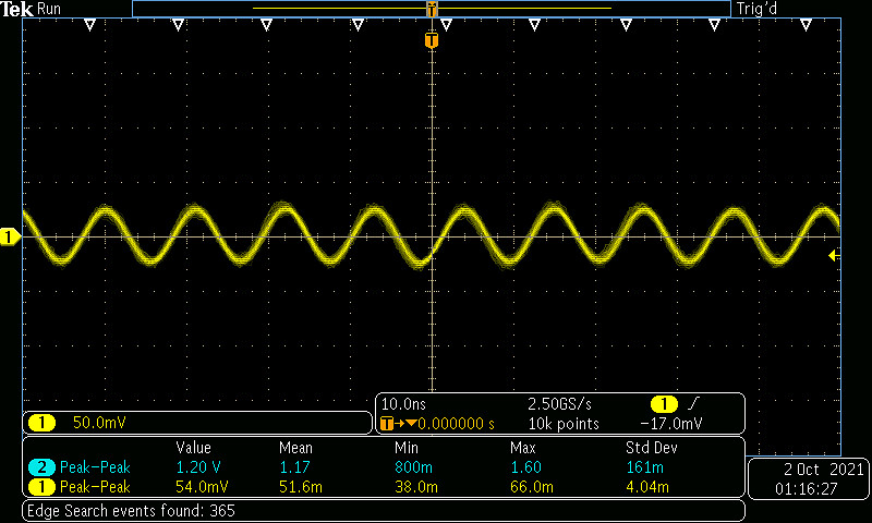
Figure 5 – Output signal from the class AB push-pull amplifier
|
Output amplitude |
2.488 Vpp |
|
Input amplitude |
1.0 |
|
Gain(V/V) |
2.488 |
Table 3.2 – Voltage amplitudes and gain for the CE/push-pull amplifier terminated in a 10Ω load.
Step 3.5b
In Part 3.5 of our lab, we used the LM386 amplifier. The LM386 is an integrated circuit amplifier designed for use in low voltage consumer applications such as audio amplifiers. It features very low quiescent power dissipation, and the voltage gain is adjustable from 20 to 200. Following the gain pin out diagram from our lab instructions, I inserted the LM386 amplifier between the generator and the speaker, this replaced my CE amp from earlier in this experiment.
I conducted a sound check with my function generator set to 10mVpp at 1 kHz. I then increased it in steps of 10mVpp up to 100mVpp. From 10-30mVpp the sound contained lots of static. Starting at 40mVpp I achieved a nice clear sound. I attached a 1.2kΩ resistor and a 10µF capacitor in series to pins 1 and 8 to increase the gain. With 0.516V going over a 99.8Ω resistor, that means the current was 5.17mA. So that means my PQ is 0.0026679 watts. Also, my input voltage is 50mVpp and my output voltage is 432.5mVpp which gives me a gain of 8.65. See waveform of output in Figure 6.
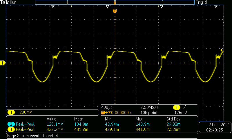
Figure 6 – Output Waveform of LM386 amplifier
Step 3.6
Operational amplifiers, or op-amps, are integrated circuits that amplify the difference in voltage at a pair of input terminals. The op-amp’s extremely high gain, high input resistance, and low output resistance allows it to most often be treated as an ideal device with some very useful properties that allow simple design of general-purpose amplifiers, buffer amplifiers, summing and difference amplifiers, integrators, differentiators and filters.
For Part 3.6b of this lab we used the TL071 op-amp. We had to breadboard the op-amp circuit of Figure 3.24 with R3=1kΩ. We then tested the circuit with a 1kHz amplitude input signal of amplitude of 10mV. My Vout was 1.855 which means I had a gain of 185.5.
Next, I added the class AB stage to my op-amp circuit as shown in Figure 3.26. I tested the circuit with a 1kHz amplitude input signal of 20mVpp, my Vout was 552.7mVpp which means my gain, Av is 27.635.
I replaced my 10Ω load resistance with my speaker. I played around with my input signal frequency and amplitude, and I received a good clear sound from my speaker. You can see a sample waveform as I tested it over my 10Ω resistor in Figure 6.
Table 3.3 compares the gain, A, and quiescent power, PQ, from my various amplifiers
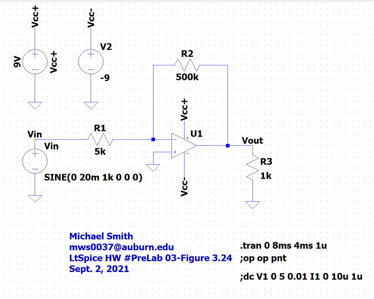 Figure 3.24 – Simple inverting op-amp circuit driving a 10Ω load.
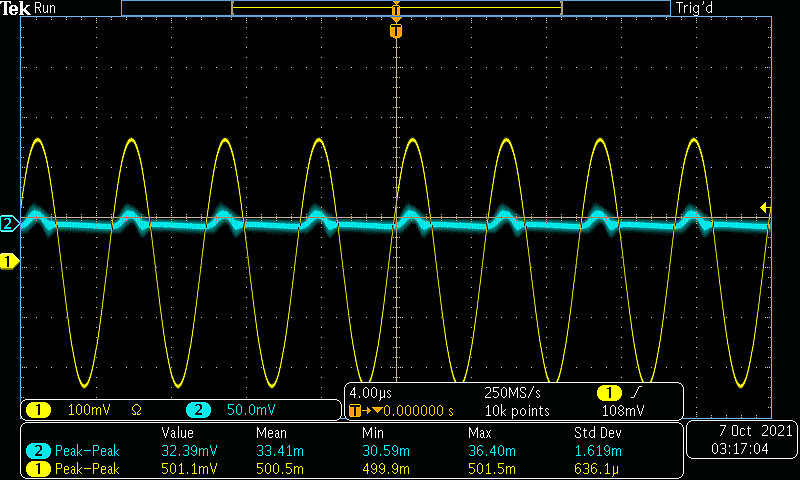 Figure 6 – Output signal using the LM386 amplifier.
|
|
Gain(V/V) |
PQ(watts) |
|
CE/CC amp |
7.0 |
0.82906858 |
|
CE/class AB amp |
2.488 |
0.00408679 |
|
Op-amp/class AB amp |
27.635 |
0.07671593 |
|
LM386 amp |
8.65 |
0.0026679 |
Table 3.3 – Gain and Quiescent PQ various amplifiers.
Conclusion
Lab 3 was extremely educational in getting experience constructing and using various Audio Amplifiers. After breadboarding, analyzing and experimenting with the Common-Collector (CC amp), CE-CC two-stage amp, Class AB push-pull amp, CE class AB two-stage amp, op-amp class AB two-stage amp and the LM386 audio amp it helped solidify the advantages and disadvantages of each amp. The goal of all these lab exercises is for us to build a working AM radio and select the best components. Through this lab, at this point, I feel I will be using the CE/CC amp because of the large gain and clear sound I received from my speaker during my experiments.