Experiment 9 - Oscillator

Michael Smith
ELEC 3030-RF Systems Lab
Date of Lab - Friday, November 5, 2021, 1 p.m.
Experiment 9 – Oscillator
Today’s Date – December 3, 2021
Introduction
In this lab exercise we had use a Hartley Oscillator as our local oscillator source for our radio. It is expected that this oscillator should produce a sinusoidal output that will be delivered to the emitter of our mixer circuit. We need to make sure the frequency of the sinusoid should be adjustable over a sufficient range to pick up all the AM radio stations of interest. In the prelab exercises we used LTspice to build a Hartley Oscillator and change several settings, each time seeing how it affected our circuit. Running these various simulations was necessary to help us see how changing the different components affected various outcomes and would help us build our own Oscillator and test the circuit in lab. I worked with my lab partner, Jordan Hutchinson, to complete this lab.
In order to cut on redundancy and reduce the addition of unnecessary images, I have labeled my images the same as the images in the lab instructions. In other words, if the lab instructions say to recreate the circuit in Figure 9.4, I have labeled the circuit I recreated from the lab instructions, Figure 9.4. Likewise, if we are to recreate Table 9.3, I have labeled my Table 9.3, same with graphs. Since the person grading this paper is very familiar with the pre-lab and lab instructions, I don’t see the need to add the images that have to be recreated when the reader has that information in front of them. Also, I feel if you must compare lab instructions of Figure 9.3 to my Figure 9.3, it cuts down on confusion of numbering and labeling.
Part 9.2 Steps 1 & 2
In the first part of our lab, we had to construct the Hartley Oscillator of Figure 9.1. The oscillator circuit can be breadboarded into the mixer circuit from Lab 08-Mixer. Next, we had to observe the output of the oscillator as we adjusted the trimmer capacitor. The frequency at the lowest range that was usable was 1.176 MHz. In contrast the frequency at the highest range that we could use was 1.76MHz. This allowed us to achieve an intermediate frequency (IF) of 200kHz for the A.M. stations that are broadcasting in the Auburn area. You can see, though, that the signals are slightly distorted, see Figures 1 and 2.
From Figures 1 and 2 you can observe we were able to achieve a frequency range that aided our oscillator circuit to work with our mixer circuit. My lab partner and I had issues creating the 3 circuits from labs 7, 8, and 9. Since we ran into issues in keeping these circuits functioning properly, we elected not to put these components into our final working radio circuit.
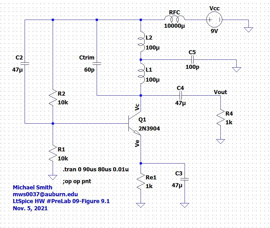

Figure 9.1 – Hartley Oscillator for LTspice simulation
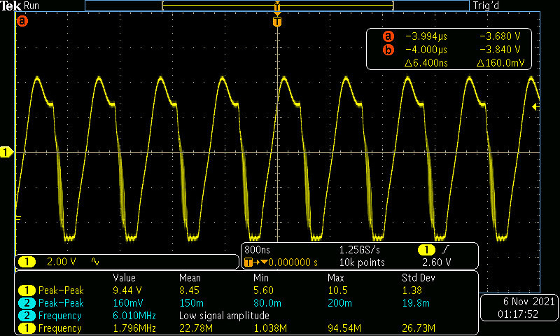
Figure 1 – Maximum Frequency
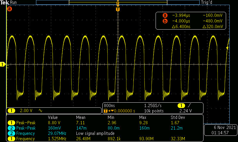
Figure 2 – Middle Frequency
Conclusion
According to oscillator theory, several parameters must be met. These prelab exercises were designed to help us see how changing certain components, changes several outcomes. These simulations helped us see what would help us achieve desirable oscillation, and what would hinder it. All of this was designed to help us make an educated decision in deciding what was the best components and sizes necessary to construct a working Oscillator to add to our AM Radio. With the completion of this final lab exercise, the heterodyne circuit for our radio is completely constructed. Each step has helped our radio to increase its performance and sound quality. My lab partner and I elected not to add the circuits constructed in our final working radio. We used an Op-Amp and achieved a working radio that exceeded our expectations. When we tried to incorporate the components from labs 7, 8 and 9, we ran into multiple problems. The final performance of the radio we constructed exceeded our expectations. The entirety of these lab experiments helped us to understand and build a working radio. Words come short in expressing my amazement of such an achievement.