Experiment 5 – RF Amplifier

Michael Smith
ELEC 3030-RF Systems Lab
Date of Lab - Friday, October 8, 2021, 1 p.m.
Experiment 5 – RF Amplifier
Today’s Date - October 12, 2021
Introduction
In our continuous project of building an AM radio, we are introduced to Common Source (CS) field effect transistor (FET) amplifier. We had projects along with modifications that we used LTspice for simulation in order to have insight before we physically constructed our circuit. Next, I will have to add the CE Amp to my circuit. All of this is to prepare us to completely breadboard the RF amplifier circuit in lab.
In order to cut on redundancy and reduce the addition of unnecessary images, I have labeled my images the same as the images in the lab instructions. In other words, if the lab instructions say to recreate the circuit in Figure 5.4, I have labeled the circuit I recreated from the lab instructions, Figure 5.4. Likewise, if we are to recreate Table 5.3, I have labeled my Table 5.3, same with graphs. Since the person grading this paper is very familiar with the pre-lab and lab instructions, I don’t see the need to add the images that have to be recreated when the reader has that information in front of them. Also, I feel if you must compare pre-lab instructions of Figure 5.3 to my Figure 5.3, it cuts down on confusion of numbering and labeling.
Part 5.5 Step 1
In step 1 of Part 5.5 of our lab I had to construct the Common Source amplifier shown in Figure 5.5, with RL=10kΩ. I then had to measure and record the Q point and the gain and in Table 5.3. I repeated these measurements for RL=1kΩ and RL=1MΩ.
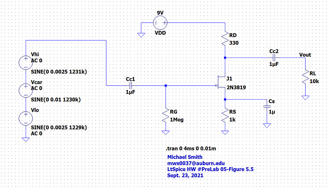
 Figure 5.5a – Common source (CS) amplifier with AM input
|
|
RL=1MΩ |
RL=10kΩ |
RL=1kΩ |
|
Q(VDS, ID) |
(1.6 V, 1.64mA) |
(1.6 V, 1.64mA) |
(1.6 V, 1.64mA) |
|
G(V/V) (no RFC) |
2.37 |
2.3 |
2.35 |
|
G(V/V) (with RFC) |
9.52 |
9.31 |
6.78 |
Table 5.3 – Measurements on CS amp
Part 5.5 Step 2
In step 2 of Part 5.5 of our lab I then added the RFC, as in Figure 5.7. I recorded the new gain for RL = 1kΩ, RL = 10kΩ, and RL = 1MΩ in Table 5.3.
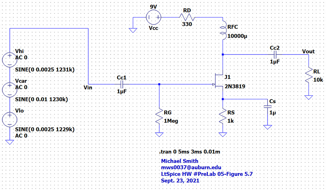 Figure 5.7a – CS amplifier after adding an RFC.
Part 5.5 Steps 3 & 4
In step 3 and 4 of Part 5.5 of our lab I added the common emitter amplifier as in Figure 5.9 and I recorded the Q point for the npn BJT. Q(npn BJT)= Q(VDS, ID)= Q(1.6V, 1.638mA). I measured the gain with various values of load resistances RL and filled out Table 5.4, you can see this data plotted in Figure 5.10.
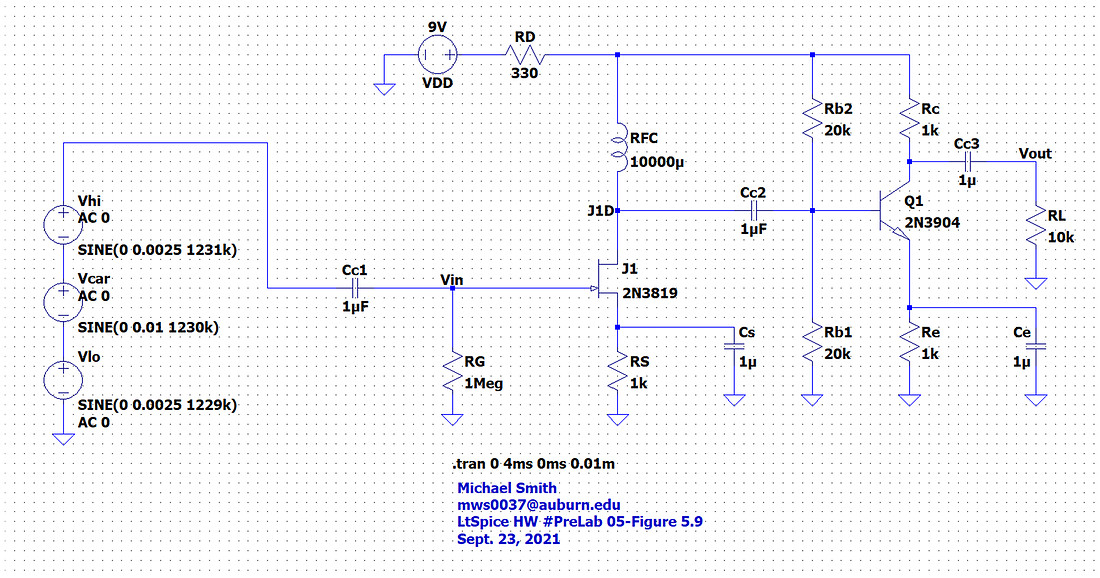 Figure 5.9a – Two stage RF amplifier (CS amp + CE amp)
|
RL |
Gain (V/V) |
Gain (dB) |
|
RL=1 MΩ |
132 |
42.411 |
|
RL=100 kΩ |
125 |
41.938 |
|
RL=10 kΩ |
120 |
41.584 |
|
RL=1 kΩ |
104 |
40.341 |
|
RL=100 Ω |
38 |
31.596 |
Table 5.4 – Gain of two-stage amp
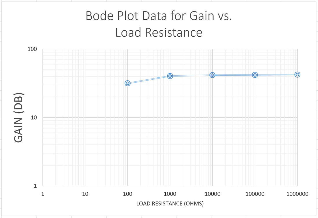 Figure 5.10 – Gain of two stage amp, data from Table 5.4
Part 5.5 Step 5
In step 5 of Part 5.5 of our lab I then breadboarded the output of the RF amplifier to the input of my detector, see Figure 5.12. I then tested my radio with the appropriate input signal. My signal and sound was nice and clear.
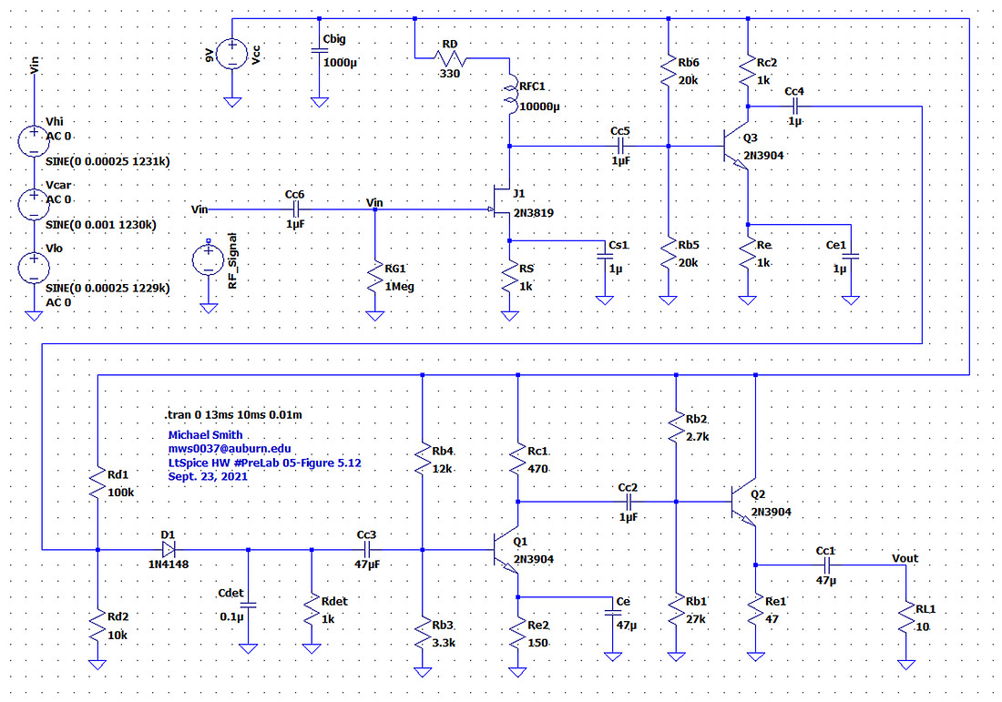 Figure 5.12a – My version of the overall simple AM Radio circuit.
Conclusion
Throughout this lab experiment we were introduced to the common source Field effect transistor (FET) amplifier. From looking at my plots from Lab 4 and Lab 5, my first inclination was to use a CFP detector. I constructed the circuit, and after running simulations and testing the constructed circuit, it was clear that it did not work as I expected. The projects we were given along with the modifications using LTspice gave me several insights of what modifications would affect my circuit and how. After breadboarding the CE Amp to my CS amp and running simulations, I saw how it added more gain in my RF amp. I saw which part would help in the construction of my final AM radio circuit. From my simulation I choose CS Amplifier with an RFC as my audio amplifier and biased diode and common collector detector circuit as my AM detector. This helped my AM radio to work extremely well. From the simulations and resulting graphs, and after I built and tested my circuit, this combination produces more desirable results for me.