Experiment 7 - Bandpass Filter

Michael Smith
ELEC 3030-RF Systems Lab
Date of Lab - Friday, October 22, 2021, 1 p.m.
Experiment 7 – Bandpass Filter
Today’s Date - December 1, 2021
Introduction
Many frequency components are contained in the output of the mixer. It is preferred that we filter out the unwanted components, otherwise we will waste power amplifying them. These unwanted frequency components can also cause noise in the output and can even result in more noise due to mixing in nonlinear devices in the circuit. The purpose of this lab is to introduce the tank circuit as a bandpass filter. We are also supposed to become familiar with bandwidth and Q of a resonant circuit. To help us better understand this, we used LTspice to analyze the filter circuits under different settings in our prelab exercises. Once we performed the necessary calculations and ran several simulations in LTspice this helped us breadboard the circuit and analyze it during our lab.
In order to cut on redundancy and reduce the addition of unnecessary images, I have labeled my images the same as the images in the lab instructions. In other words, if the lab instructions say to recreate the circuit in Figure 7.4, I have labeled the circuit I recreated from the lab instructions, Figure 7.4. Likewise, if we are to recreate Table 7.3, I have labeled my Table 7.3, same with graphs. Since the person grading this paper is very familiar with the pre-lab and lab instructions, I don’t see the need to add the images that have to be recreated when the reader has that information in front of them. Also, I feel if you must compare pre-lab instructions of Figure 7.3 to my Figure 7.3, it cuts down on confusion of numbering and labeling.
Step 7.1 Part 1 & 2
The first goal to accomplish was to physically construct the circuit as in Figure 7.3 with the specified values. Then we had to use the signal generator to provide a variable frequency input signal and use the dual trace feature of our oscilloscope to observe the input and output signals simultaneously, see Figure 1. In our circuit we changed several parameters such as the Lfl, Cfl, RL and RS. With each change we used the measured values to find the upper and lower corner values and to calculate and record the fres and Q. For all the different parameters and resulting calculations see Table 7.2.
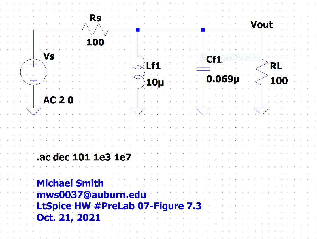
 Figure 7.3 - The default LTspice Circuit
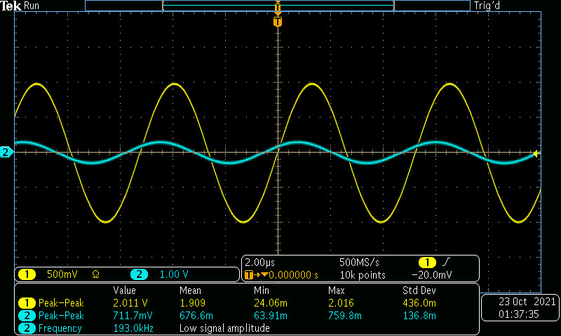
Figure 1- Example Input and Output signals of Circuit from figure 7.3
Step 7.1 Part 3
In part 3 of this lab experiment we continued to work with the circuit we constructed in Figure 7.3. We were instructed to replace RS and RL with 1kΩ resistors and record how that effected our circuit’s fres and Q. We were then encouraged to also change the Lfl and Cfl and notice the resulting effects on our circuit. For a complete list of the different parameters, I changed and the resulting effects on the upper and lower corner values, fres and Q, see Table 7.2 below.
|
Lfl |
10µH |
10µH |
100µH |
100µH |
100µH |
|
Cfl |
0.069µF |
0.069µF |
0.069µF |
0.022µF |
0.022µF |
|
RL, RS |
100Ω |
1kΩ |
100Ω |
100Ω |
1kΩ |
|
fres |
214kHz |
214kHz |
69kHz |
126kHz |
122kHz |
|
f(-3 dB, low) |
185kHz |
206kHz |
48kHz |
71kHz |
110kHz |
|
f(-3 dB, high) |
247kHz |
224kHz |
100kHz |
218kHz |
136kHz |
|
BW |
62kHz |
18kHz |
52kHz |
147kHz |
26kHz |
|
Q=fres/BW |
3.452 |
11.889 |
1.3269 |
0.8571 |
1.6923 |
Table 7.2 – Measurement Data
Conclusion
In changing different aspects of our circuit, it became clear that changing the values of the resistors while maintaining the inductor and capacitor values we get a different bandwidth. In other words, values of L and C modify the center frequency and changing the resistors changes the bandwidth. This is very helpful in creating a cleaner signal that we can hear from the speaker of our A.M. radio. In our continuous pursuit of building a better AM radio, we need to consider many factors. If we are trying to amplify a frequency, we don’t want to amplify unnecessary components. It is good that we were introduced to bandpass filters for our radio in order to get the cleanest signal we can out of the speaker. This lab was very educational and introduced me to several concepts I had not considered until now.