Experiment 6 - Square Loop Antennas

Michael Smith
ELEC 3030-RF Systems Lab
Date of Lab - Friday, October 15, 2021, 1 p.m.
Experiment 6 – Square Loop Antennas
Today’s Date – November 10, 2021
Introduction
A variety of antenna architectures have been used for A.M. reception. The purpose of this lab is to design and construct a square loop antenna. We also must use known formulas to calculate various parameters for us to tune the antenna for optimum reception. Certain items were suggested before we started this lab. One was to use a square pizza box for convenience and to save on cost. Also, that our primary objective is to be able to pick up the A.M. station 1230 kHz. So, with these suggestions and details I calculated in my prelab report, I began the work to construct a square loop antenna and to complete my working A.M. radio and to pick up A.M. station 1230 kHz.
In order to cut on redundancy and reduce the addition of unnecessary images, I have labeled my images the same as the images in the lab instructions. In other words, if the lab instructions say to recreate the circuit in Figure 6.4, I have labeled the circuit I recreated from the lab instructions, Figure 6.4. Likewise, if we are to recreate Table 6.3, I have labeled my Table 6.3, same with graphs. Since the person grading this paper is very familiar with the pre-lab and lab instructions, I don’t see the need to add the images that have to be recreated when the reader has that information in front of them. Also, I feel if you must compare lab instructions of Figure 6.3 to my Figure 6.3, it cuts down on confusion of numbering and labeling.
Step 6.1b Part 1 & 2
To help me better prepare for lab 6, I went ahead and measured my box for length (A) and width (B). I performed various calculation to see how to achieve optimal results.
I calculated what the inductance required for the middle station (1400kHz), using a 60pF capacitance, which is roughly the middle of my trimmer value. The resulting calculation was 208.0007 µH.
Now that I have the inductance required, I needed to calculate the number of turns around my square loop to get close to this inductance. The resulting number of turns is 16.
Knowing I needed to achieve an inductance of 208.0007 µH, I needed to see what capacitance was required to pick up the lowest frequency station (1230kHz). Using my MATLAB program, I calculated the resulting capacitance to be 80.4943pF. This will be the maximum capacitance that I will need.
I also calculated the lowest capacitance that I needed to be 52.7094pF to pick up the 1520kHz station. I need to achieve a range of 52.7094pF - 80.4943pF and the trimmer capacitor has a range of 8.5 to 120 pF. From my calculations my trimmer capacitor can handle the range required. I will not need to add a capacitor in parallel.
From all the parameters above I decided to use 16 windings on my box. Also, to help save on lab time and expedite the process, I went ahead and cut 16 slits on the side of my pizza box and brought in tape to secure the windings in place. I knew I would need my lab partner’s help in wrapping the wire around my box.
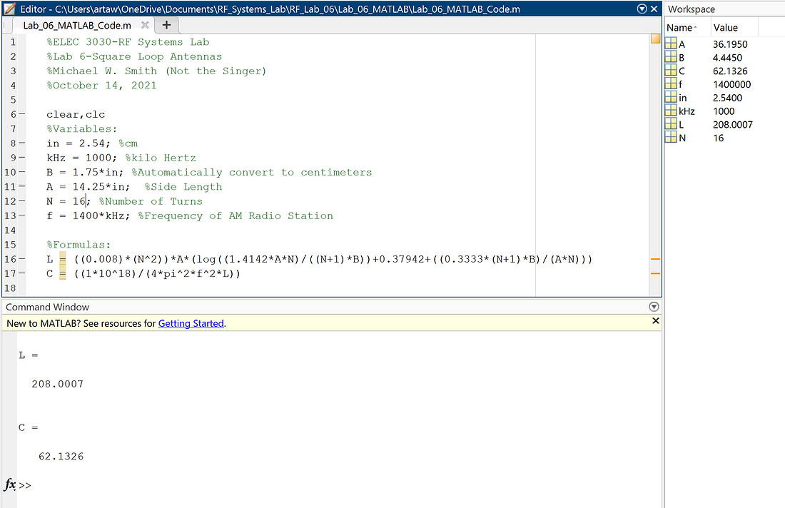
 Figure 1 – MATLAB code to Calculate Inductance (µH) and Capacitance (pF) for my Pizza box
Step 6.1b Part 5
After Calculating the number of turns and then physically constructing our antenna we needed to attach it to our circuit, see Figure 7. To get a better understanding of our circuit, with the antenna attached, we connected it to an oscilloscope and ran a RF Spectrum Analyzer. To test this, we adjusted the center frequencies to the values as shown in Table 6.2. With each frequency we had to adjust our trimmer capacitor to get the maximum value, this also gave us the power level in dBm which is also recorded in Table 6.2. From this information we could calculate the Amplitude Voltage (Vamp), also recorded in Table 6.2. The corresponding waveforms from the Oscilloscope can be seen in Figures 2 - 6. This gave us the information needed so that we could achieve the necessary power levels for different frequencies without having to making changes to our antenna. This verified that we had built our antenna correctly and helped us move on to the next step, making sure our antenna could pick up an A.M. radio frequency.
|
Frequency (kHz) |
Power level (dBm) |
Vamp (µV) |
Corresponding Waveform |
|
1230 |
-55.3 |
543.3 |
Figure 2 |
|
1315 |
-55.8 |
512.9 |
Figure 3 |
|
1400 |
-55.7 |
518.8 |
Figure 4 |
|
1460 |
-55.9 |
507 |
Figure 5 |
|
1520 |
-55.9 |
507 |
Figure 6 |
Table 6.2 – Measured Power Level at 1230 kHz and Other Frequencies of Interest
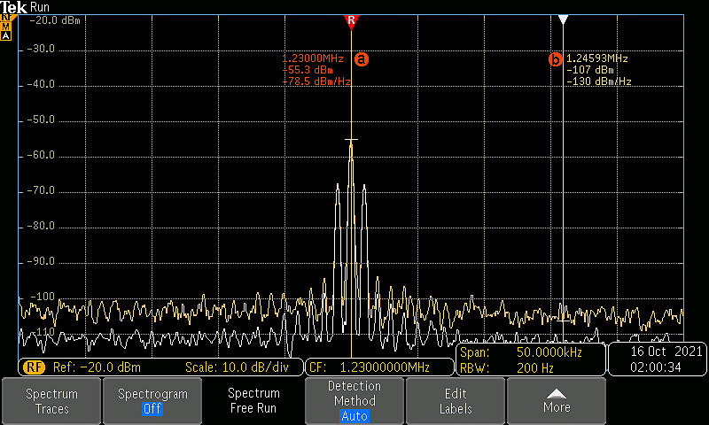
Figure 2- Spectrum Analysis for 1230 kHz
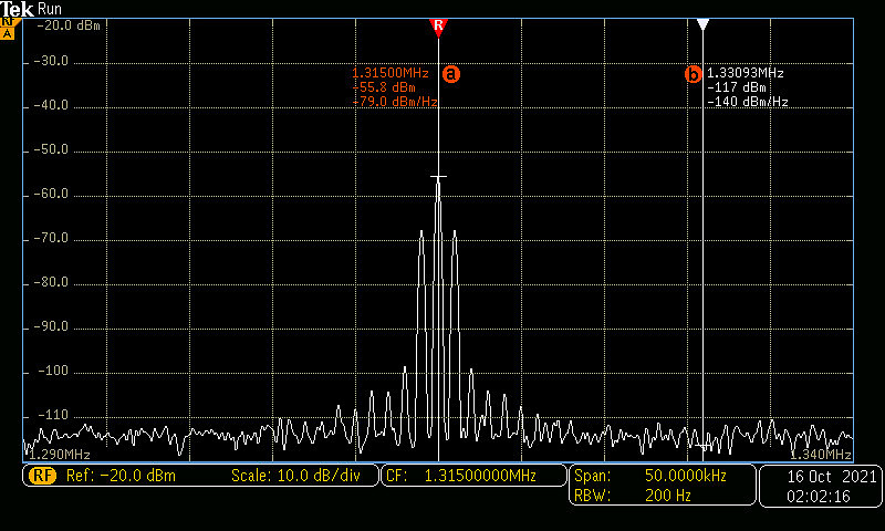
Figure 3- Spectrum Analysis for 1315 kHz
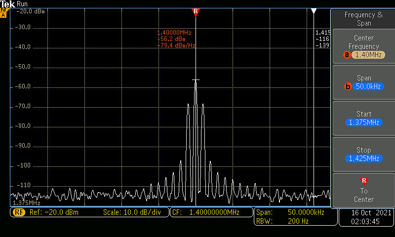
Figure 4 - Spectrum Analysis for 1400 kHz
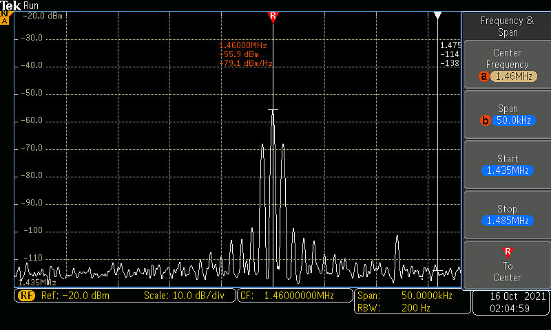
Figure 5 - Spectrum Analysis for 1460 kHz
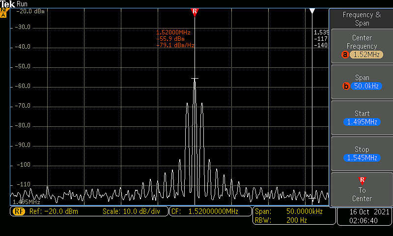
Figure 6 - Spectrum Analysis for 1520 kHz
Step 6.1b Part 6
With all the preparation and testing of our circuit behind us, it was time to see if the circuit worked. We plugged in our antenna and adjusted our trimmer capacitor, and we were able to pick up A.M. Station 1230. The circuit and antenna worked well. From the speaker you could hear some static, with a few adjustments we reduced the static and were able to hear the radio station. The circuit could be improved with the addition of some filters, but overall, I was happy with our results. To see our circuit working, watch the video below, Figure 8.
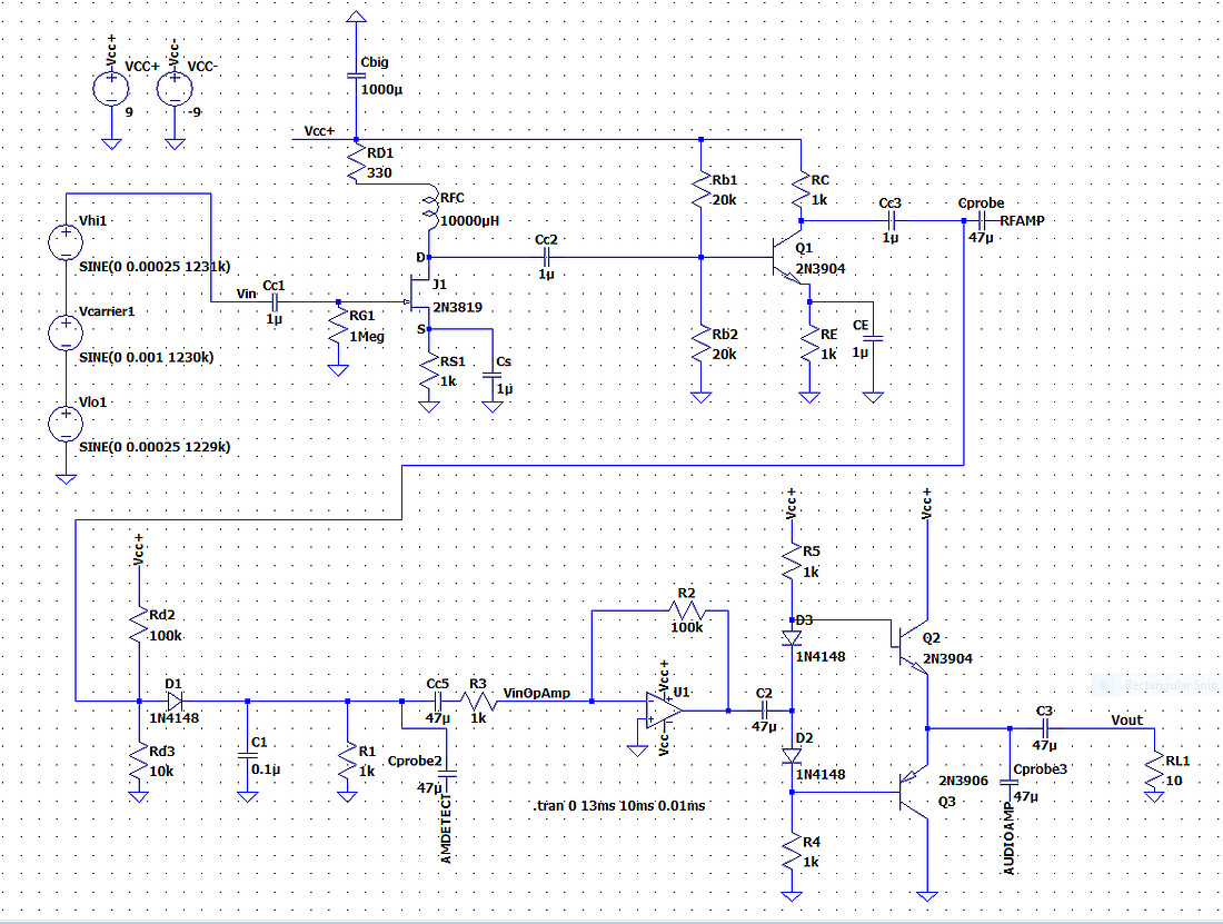 Figure 7 – Our final circuit design
Figure 8 - Video or our radio with antenna attached and picking up station A.M. 1230
Conclusion
I enjoyed this lab experiment more than any of the others. It is extremely satisfying seeing several weeks of work come to fruition in a fully functional radio. The radio does have room for improvement, which I feel the following labs will help us improve. Now that we have a completely working radio I really look forward to our future labs and fine tuning this fully functional device that we have constructed.